Flight Instruments: The Six Pack
Student pilots will operate a variety of aircraft to obtain and further their flight knowledge. Safe operation of an aircraft involves a pilot’s ability to understand flight instruments and to recognize what to do if they aren’t working properly. Let’s take a look at the standard flight instruments that make up a plane’s six pack and determine how they’re used in the air.
The Six Pack: Basic Flight Instruments
The “six pack” references the six main flight instruments in a cockpit, displayed with three instruments stacked on top of three other instruments. While three of the six instruments belong to the plane’s Pitot-Static Pressure System, the other three are considered Gyroscope Instruments. It’s essential for pilots to know what each of these instruments are and how to read them properly as they soar through the sky.
Pitot-Static Flight Instruments
The pitot-static flight instruments are sensitive to pressure from the plane’s motion through the air and are attached to the pitot-static system of the aircraft.
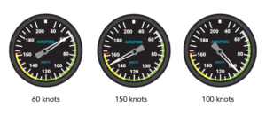
- Airspeed Indicator
An airspeed indicator measures an airplane’s airspeed. As your airspeed changes, the needle on the indicator’s dial moves to match the airspeed. Essentially, the airspeed indicator works by moving air pressure from the pitot tube to static pressure from one or more static ports. These indicators are color-coded so that a pilot can recognize its operating range. Green signifies normal operating range, white indicates the flap operating range in which flaps can be utilized safely, yellow for caution range and a red line shows the maximum speed that may not be exceeded.
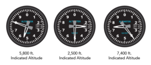
- Altimeter
An altimeter measures the aircraft’s height above mean sea level (MSL), which is corrected for atmospheric differences. Sealed aneroid wafers, or disk-shaped capsules, are the main components in an altimeter. These wafers enlarge and contract according to changes in static pressure, similar to a barometer. Higher pressure causes the wafers to collapse, while a lower pressure expands the wafers. Compressed wafers show a decrease in altitude and expanded wafers show an increase in altitude. These actions allow the needles on the altimeter’s face to move, which is what the pilot reads. The altimeter has two pointers on its face. Reading the altimeter like a clock, the shortest needle, or the “hour” hand, represents 1,000 feet and the long pointer, or “minute” hand, exemplifies 100 feet. As an example, 5,500 feet is represented as the short needle between 5 and 6 and the long pointer on 5.
- Vertical Speed Indicator
The vertical speed instrument determines the rate of an aircraft’s climb or descent, measured in feet per minute (fpm). This indicator measures and compares static pressure inside of a diaphragm, which changes as the aircraft climbs or descends. The pressure difference is linked to the needle on the face of the indicator, which moves up with climb and down with descent. If a pitch is held constant, the pointer will stabilize and display the rate of climb in hundreds of fpm.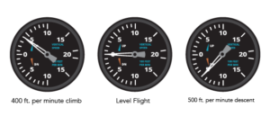
Gyroscopic Instruments
Gyroscope instruments are either vacuum, electric or pressure powered.
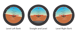
- Attitude Indicator
Using an attitude indicator, an aviator can determine if the aircraft is descending, climbing, straight and level or turning. It shows changes in pitch and bank attitude. The attitude indicator shows a depiction of an airplane in level flight that corresponds with the aircraft’s movement and displays its relation to the horizon. Most indicators will have bank increments of 10, 20, 30, 45, 60 and 90 degrees. The center of the depiction represents an aircraft’s pitch and will move accordingly.
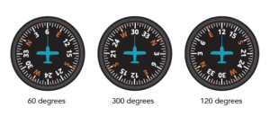
- Heading Indicator
The heading indicator uses a rotating gyro which informs the pilot of an aircraft’s direction, similar to a magnetic compass. The indicator displays headings based on a 360-degree azimuth. An image of a small aircraft is centered on this instrument and turns with the motion of the plane.
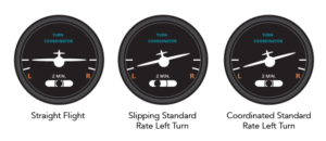
- Turn Coordinator
During a turn, an airplane will roll and yaw at the same time, which is why a turn coordinator is important. A turn coordinator displays initial roll rate and then turn rate when a roll is stabilized. A small airplane depiction is also shown on these flight instruments, displaying rolls along with the plane’s movement to show the turn direction. A small ball underneath the airplane depiction moves along with the yaw of the airplane in an inclinometer or “balance indicator”. When rolling in or out of a turn, the small airplane banks in the direction the plane rolls.
Having knowledge of each of the flight instruments in a six pack makes for a well-rounded, prepared pilot.
Flight Training in the Six Pack
Throughout the PPL Course at AeroGuard, students utilize Piper Archer planes equipped with six pack flight instruments. Utilization of the six pack flight instruments helps create a strong foundation for pilots in training, as they’ll build upon their knowledge and will progress to G-1000 aircraft later in their training.